 English
 русский
 Español

If your classroom has one demonstration generator and ten minutes, the version worth buying has three visible parts: a coil you can watch turn, a magnet whose field you can disturb, and a pointer that swings in both directions. Everything else — the digital readout, the moulded housing, the printed worksheet — is decoration.
That is the short answer. The longer answer is that many "AC/DC generator" sets sold to schools light a small lamp and stop there. A lamp cannot show direction, cannot show a zero crossing, and cannot show the exact moment the flux stops changing. For a lesson on electromagnetic induction, those three moments are the entire lesson.
What follows covers what the demonstration must make visible, three setups that survive real classroom use, a ten-minute run sheet, the equipment failures that flatten the demo halfway through, and the specifications worth writing into a purchase order.
What the demonstration has to make visible
Three observations carry the physics, and each one needs its own beat in the lesson rather than being bundled into a single "look, it works" moment.
- Zero output with a static field. Lock the rotor, keep the magnet in place, and the meter reads nothing. A strong field is present, yet no EMF appears, because induced EMF depends on the rate of change of flux linkage, not on the flux itself. Students who see this once stop confusing "magnet nearby" with "voltage produced".
- A reversal every half turn. With slip rings, the pointer crosses zero twice per revolution. That crossing is the visible signature of alternating current, and it is far more convincing than the word "AC" printed on a label.
- Output that follows speed. One revolution every two seconds gives a modest deflection; doubling the speed roughly doubles the peak value until the iron starts to saturate. Suddenly "rate of change" stops being an abstract phrase.
A unit that hides its coil inside an opaque case, or that drives an internal lamp with no external terminals, can only prove that something happened. It cannot show why, and it cannot be reconnected for the second half of the lesson.
 Open Coil Electromagnetic Induction Apparatus for Teaching LabsExposed 10 Ω winding, hand-turned shaft and labelled output terminals make induction visible and let students reconnect the experiment.View Product →
The most useful hardware is therefore deliberately plain: an exposed coil of a few hundred turns, a pair of pole pieces on a yoke, a shaft you can turn by hand, and clearly labelled output terminals that accept 4 mm banana plugs.
Three setups that fit a normal classroom
Not every school can buy a projection meter and a data logger in the same year. These are the three realistic options, compared on what decides whether the lesson lands: what students can actually observe, how quickly it sets up, and what wears out first.
| Setup | What students can see | Best suited to | What wears out first |
|---|---|---|---|
| Hand-crank magneto driving a lamp | Brightness rising and falling with crank speed; no direction, no zero crossing | Lower secondary introduction to energy conversion | Brushes and the drive belt |
| Rotating coil between permanent magnets with a center-zero meter | Pointer swinging left and right, passing through zero twice per revolution; sine-like output on a scope | Teaching AC, slip rings, and the idea of a waveform | Slip-ring contact surfaces and brush pressure |
| Small DC motor driven backwards, feeding an LED | A unidirectional output that only lights the LED above a threshold speed | Showing DC generation and the commutator idea cheaply | The motor's own brushes; fragile leads |
If only one set fits the budget, choose the rotating-coil type supplied with both slip rings and a split-ring commutator. It is the only one of the three that shows AC and DC emerging from the same coil, minutes apart, without the class changing benches.
A ten-minute run sheet
Sequence matters more than equipment. Each step below produces exactly one observation, in the order students can absorb it.
- Start locked. Hold the rotor still with the magnet in position and ask what the meter should read. The answer is zero, and the silence that follows is the useful part.
- Turn one revolution every two seconds by hand. Ask students to count how many times the pointer crosses zero. They should see two crossings per revolution, and someone will usually say "it went the other way" before you say "alternating".
- Speed up. Peak deflection increases; note aloud that the field strength never changed, only the rate at which the coil cut it.
- Swap to the split-ring commutator, or rotate the changeover drum if your set has one. The pointer now stays on one side, but pulses rather than holding steady — a pulsating DC at twice the rotation frequency.
- Add a load. Connect a 2.5 V lamp or an LED with a series resistor, and let students feel that the crank becomes harder to turn once the circuit closes. That resistance is Lenz's law in the wrist, and it lands better than any diagram.
- If a data logger or oscilloscope is available, repeat step 2 and step 4 on screen. The sine wave and the pulsing half-waves sitting side by side settle the difference between AC and DC in one glance.
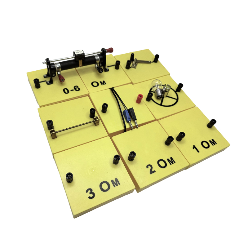 Demonstration Electrical Circuit Set for Junior High PhysicsComplete bench set for direct-current circuit demonstrations, with power, breaker, resistor, potentiometer and 12 V lamp for ordered experiments.View Product →
Keep one group set wired in parallel with the demonstration bench so a student can reproduce the crank-and-meter sequence while the rest of the class watches. Two pairs of hands at the front keeps attention far better than one teacher talking over a spinning rotor.
Making the pointer readable from the back row
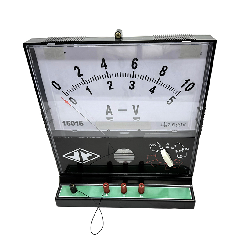
A 60 mm panel meter is adequate at a bench and invisible from the back of a class of 32. There are two practical fixes: a projection meter placed on an overhead projector or document camera, or a large-scale demonstration meter with an 80–100 mm dial and heavy, well-damped movement.
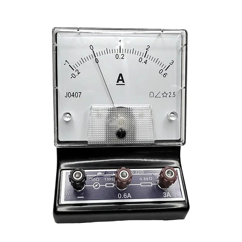
Whatever you choose, insist on a center-zero movement. A standard moving-coil DC voltmeter deflects in one direction only; when the EMF reverses, the pointer simply rests against the stop and the reversal — the whole point of the AC portion of the lesson — becomes invisible. A ±5 mA or ±100 mV center-zero movement, typically to class 2.5 accuracy, is precise enough for teaching and considerably more robust than a digital display that flickers too fast to read aloud.
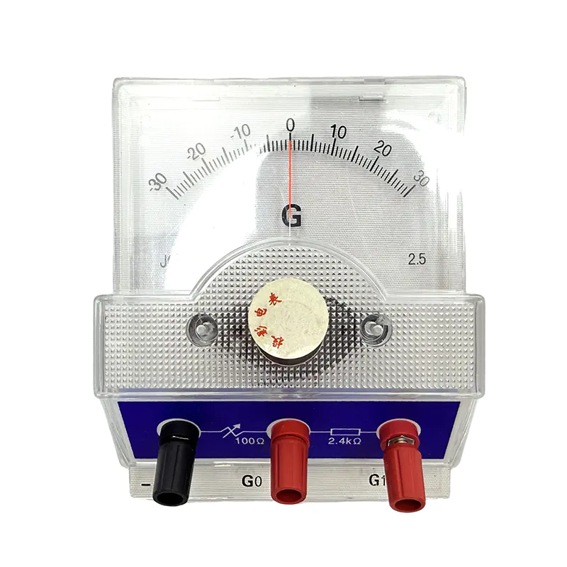 Center-Zero Projection Galvanometer for Physics DemonstrationsCenter-zero movement and 50 mm pointer make reversal visible during induction and DC experiments; projected display suits class demonstrations.View Product →
Two smaller habits help. First, mark the zero position with a strip of tape so students can see how far the pointer travels in each direction. Second, keep the meter away from the coil's own stray field; a meter sitting 150 mm from a strong magnet will show a small offset before the crank is even touched.
Where school generator demonstrations fail
- The wrong meter. A unidirectional DC meter hides every reversal. This is the single most common reason an AC demonstration looks like a broken DC one.
- Dirty slip rings and tired brushes. Oxide film on the rings adds resistance and produces an intermittent needle. Clean contact surfaces with a pencil eraser or fine abrasive before each term, and keep two spare brush sets in the storage case.
- Too wide an air gap. Field strength at the coil falls quickly with distance. Aim for the smallest gap that still lets the rotor turn freely, usually 3–5 mm between pole face and coil.
- Spinning too fast too early. A rotor at three revolutions per second produces a blur, not a lesson. Slow first, then fast, and narrate what students should be watching.
- No load, no consequence. With open terminals there is no current and no opposing torque; the demonstration feels like a toy. A lamp or LED makes the energy transfer visible and gives the crank a weight students can feel.
- Long, thin connecting leads. A metre of thin wire adds enough resistance to dim a small lamp noticeably. Use short, thick, 4 mm plug leads and keep the meter close to the machine.
What to write into the purchase order
Purchase specifications for teaching equipment tend to be vague, which is how schools end up with a sealed box that cannot be repaired. These are the lines worth stating explicitly.
- Coil of 300–600 turns, visible through a transparent former, with clearly marked terminals.
- Both a slip-ring assembly and a split-ring commutator supplied with the unit, or a single changeover drum.
- Center-zero demonstration meter included, or a projection meter offered as an accessory.
- Hand crank with reduction gearing, plus an optional motor drive for hands-free waveform work.
- 4 mm colour-coded terminals, spare brushes, spare lamps, and a storage case that protects the shaft.
- Documentation and labels in the language of instruction, with a parts list for reordering consumables.
The instruments in our physics teaching instruments range are built on this pattern — exposed working parts, replaceable consumables, terminals that accept standard laboratory leads. Manufacturing is carried out in a 10,000 m² facility under ISO 9001, ISO 14001 and GB/T 28001 management systems, and units ship to schools across Europe, the Americas, the Middle East, Southeast Asia, Africa and South America, so a replacement brush ordered three years later is a realistic request rather than a hopeful one.
Questions we are asked most often
Can a small DC motor be used as the generator?
Yes, and it is a cheap way to show DC generation. Expect only a few volts at high spin speeds, so use a 1.5–3 V motor with an LED and a series resistor, or a 1.5 V lamp. Spin it by hand through a rubber wheel rather than directly on the shaft.
Why does the pointer not move at all?
Check three things in order: the circuit is closed through the meter, the rotor is actually turning relative to the magnet, and the meter is a center-zero type rather than a one-direction DC movement. A static magnetic field alone will never produce a deflection.
Is the output of the commutator version true DC?
No. It is unidirectional but pulsating, with two pulses per revolution for a single coil. Real steady DC needs many coil segments or a smoothing capacitor, and saying this out loud prevents a common misconception.
How many turns should the demonstration coil have?
Between 300 and 600 turns is the practical window. Fewer turns give a deflection too small to read from the back row; far more turns raise the coil's resistance and make the lamp dimmer under load.
A generator demonstration earns its place in the timetable when the class can see the field do nothing, the motion do everything, and the pointer reverse on cue. Buy for those three moments — visible coil, center-zero meter, both slip rings and commutator — and the lesson takes care of itself.
If you are specifying equipment for a new laboratory or replacing a set that never quite worked, contact our team with the class level and the number of student groups, and we will match the coil, meter and drive configuration to your syllabus.