2026-11-13
Content
A technician sets up a 1.5 m air cushion guide rail, launches a glider, and gets accelerations that scatter by 8 percent between runs. The track looks straight, the glider floats freely, and nothing appears broken, yet the numbers will not support a clean Newton's second law conclusion. In most cases like this, the rail is not the problem, the air film, the leveling and the timing chain are.
An air track only delivers usable results when three conditions hold at the same time: the track is level to within a fraction of a millimetre over its full working length, the air supply produces a stable film under the glider's full weight, and the timing device matches the speeds you actually measure. Meet those conditions and a mid-range classroom rail will reproduce g·sinθ to within 2 or 3 percent, which is far more than enough for teaching and perfectly adequate for introductory lab reports.
An air cushion guide rail is a hollow extruded beam with rows of small holes along its top surface. Air pushed into the beam escapes upward and forms a thin film, typically 0.05 to 0.10 mm thick, on which the glider floats. The effective friction between glider and rail drops to roughly one thousandth of the glider's weight, which is why the setup can demonstrate inertia, momentum and energy conservation far more convincingly than a trolley on a wooden ramp.
The consequence that surprises new users is sensitivity. Because friction is nearly gone, a tilt of only 0.1 degree produces an acceleration of about 0.017 m/s². Over a 1 m run the glider picks up visible speed from a slope you cannot see by eye. That is the whole point of the apparatus, and also the reason a poorly leveled rail produces data that looks like instrument failure.
Two smaller effects are worth knowing before you blame the supplier:
A single guide rail with a pair of photogates and a set of glider masses covers most of the mechanics syllabus. The experiments below are the ones teachers actually run, listed with the measurement that decides whether the result is usable.
 X0392 Collision Test Device for Momentum ConservationSchool physics lab teaching device with an aluminum track and balls of equal size but different masses for student group momentum-conservation experiments.View Product →
| Experiment | Core measurement | Realistic classroom accuracy | Frequent pitfall |
|---|---|---|---|
| Uniform motion and velocity | Flag width divided by gate time | 2 to 3 percent | Flag not fully through the gate |
| Newton's second law | Acceleration versus applied force | 3 to 5 percent | Ignoring pulley friction and string mass |
| Momentum conservation | Velocities before and after collision | 3 to 6 percent | Bumpers not aligned with the track axis |
| Energy conversion | Spring energy versus kinetic energy | 5 to 8 percent | Spring not returned to the same release point |
| Simple harmonic motion | Period versus oscillating mass | 2 percent on period | Springs not matched in stiffness |
| Acceleration due to gravity | Acceleration versus incline angle | 3 to 5 percent | Angle measured on the frame, not the rail surface |
Skip the leveling ritual and everything after it is guesswork. The most reliable method uses the glider itself as a level indicator. Place it at the centre of the track, give it no push, and watch for 30 seconds. A drift of more than about 2 mm over 1 m corresponds to roughly 0.1 degree of tilt and should be corrected before any data is taken.
Adjust one foot at a time, then repeat the check at both ends of the track. Checking only the middle hides a twisted beam, which shows up as acceleration that differs depending on which half of the rail you use. On rails longer than 1.5 m, the twist check matters more than the absolute level, because a consistent slope can be measured and corrected in the analysis while a twist cannot.
Air supply is the second variable. Most classroom blowers run in the 3 to 8 kPa range. More pressure gives a thicker film and lower drag, but also more turbulence, more noise and more drift from escaping air. Less pressure lets the glider skim the surface, and the resulting friction is erratic rather than constant, which is worse than a simple offset. Let the blower run for a few minutes before the first measurement, confirm the hose seats firmly, and check that the working holes are clear of dust and chalk.
Two timing approaches dominate school labs, and they behave differently. Photogates measure the time a flag of known width blocks a beam, giving velocity directly. A digital timer with photogates resolving to 0.1 ms is comfortable for glider speeds from 0.1 to 2 m/s, which covers nearly every experiment listed above.
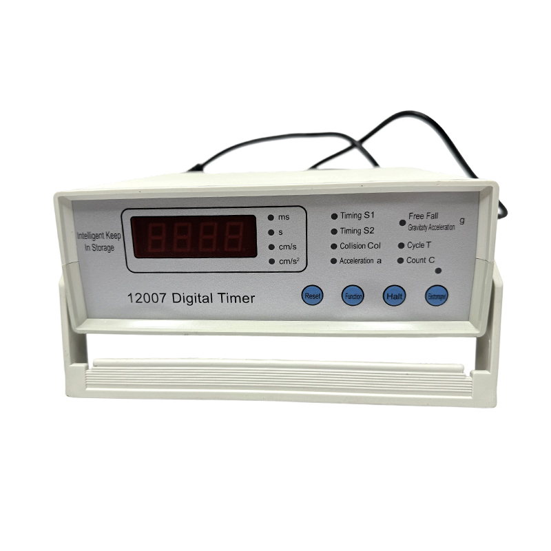 Digital Timer with Photogates for Physics LabsModel X0103 precision timer with 0.1 ms resolution, LED display, and data storage for photogate timing in school mechanics experiments.View Product →
Dotting timers remain common because they are inexpensive and produce a permanent paper record. At 50 Hz the interval is 0.02 s, so a 0.5 m fall yields a readable trace with about 25 intervals. The catch is that the paper tape adds drag, and on a near-frictionless rail that extra drag is no longer negligible relative to the forces being measured. Use the dotting timer for qualitative work and photogates for anything quantitative at low acceleration.
 Electromagnetic Dotting Timer for School Physics ExperimentsModel X0402 timer with hammer, carbon paper, and paper tape for tracking object motion and measuring time in high school physics laboratories.View Product →
Whichever device you use, measure the flag width with a caliper rather than trusting the nominal value, and count every moving mass: glider, flag, added weights, and the hanging mass on the pulley side. A 50 g hanging mass accelerating a 250 g glider is a very different experiment from the same force applied to a 400 g glider.
Teachers often expect agreement to within 1 percent because the track is "frictionless". A realistic budget for a classroom rail looks like this:
| Source | Typical size | How to control it |
|---|---|---|
| Residual tilt | 0.05 degrees gives about 0.009 m/s² | Drift test at both ends of the track |
| Timing resolution | Under 1 percent at normal speeds | Keep gate intervals longer than 50 ms |
| Pulley and string | 2 to 5 percent at small hanging masses | Increase hanging mass or correct analytically |
| Air film drift | Repeatable offset in one direction | Reverse the run direction and average |
| Mass measurement | Under 1 percent with a 0.1 g balance | Weigh the complete moving assembly |
Almost always residual tilt or asymmetric airflow. Run the drift test, reverse the glider's orientation, and if the drift follows the direction rather than the glider, the track is out of level.
Yes, using a dotting timer and paper tape, but expect 5 to 8 percent scatter instead of 3 to 5 percent because the tape adds drag to both gliders.
Yes. Leveling is a property of the surface the rail rests on, so any relocation requires the drift test again. Allow the rail to settle for a few hours after moving it between rooms with different floor temperatures.
Enough that the glider floats with a faint, steady clearance and no scraping sound. Increase pressure only until drag stops falling with further increases, since extra pressure mainly adds noise and drift.
An air cushion guide rail is a precise instrument wrapped in a simple-looking aluminium beam, and it rewards a disciplined setup routine more than a generous budget. Level it at both ends, stabilize the air supply, choose timing that suits the acceleration you are measuring, and count every moving mass. Do that and the same rail will carry a class through velocity, Newton's second law, collisions, energy conversion and simple harmonic motion with results that hold up under scrutiny. Schools building or refreshing a mechanics laboratory can review the full physics teaching instruments range to match rail length, glider sets and timing devices to their actual experiment list.
Recommended Products


+86-18630650508 +86-0574-62500588

+8618630650508

 No. 588, Chaoyang South Road, Ditang Street, Yuyao, Ningbo City, Zhejiang Province, China


 English
 русский
 Español
